Ok let move on at part 2 of the Iot for noob series. In this blog, we’ll install software to connect esp32 to our computer. Upload code to it then try to program a simple led blinking.
1. Software installation
- Install ardunio ide (we do not using this ide for code) but we use it to install driver LOL :v
- https://www.arduino.cc/en/software/ go to this link and download the version based on your OS (window or linux)
- If in linux you can download AppImage file and follow this tutorial to run an app using AppImage: https://www.itprotoday.com/development-techniques-and-management/why-and-how-use-appimage-ubuntu
- Open arduino IDE after installed then click ok if any alert box appears to install drivers
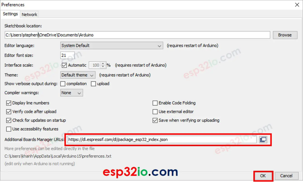
- After the installation finish. paste this line https://dl.espressif.com/dl/package_esp32_index.json in File >> Preferences
- Next install ESP32 board library in Tools => Boards => Board Management Search for esp32 and install the option from Espressif system
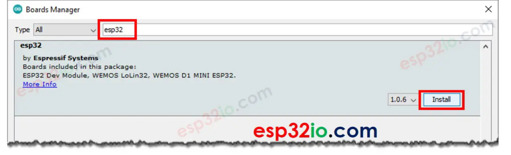
- Wait till the installation end the we can close the Arduno ide. Restart our computer then move on next step
- Install PlatformIO ideo on vscode. Why use PlatformIO instead of Ardunio IDE well because it easier with code intellisence, and because it’s an vscode extension we can code with github copilot too 😀
- https://platformio.org/
- Also you can visit these site: https://docs.espressif.com/projects/esp-idf/en/latest/esp32/get-started/#installation then follow these steps to install driver for esp32
- And follow this link https://docs.espressif.com/projects/esp-idf/en/latest/esp32/get-started/establish-serial-connection.html to check the serial port on your computer usually on window is COM3 and in linux is /dev/ttyUSB0
- Note: you need to connect the board to PC to check the port. COM1 is not for serial port so it can not send serial data (serial port is what i’ll explain later)
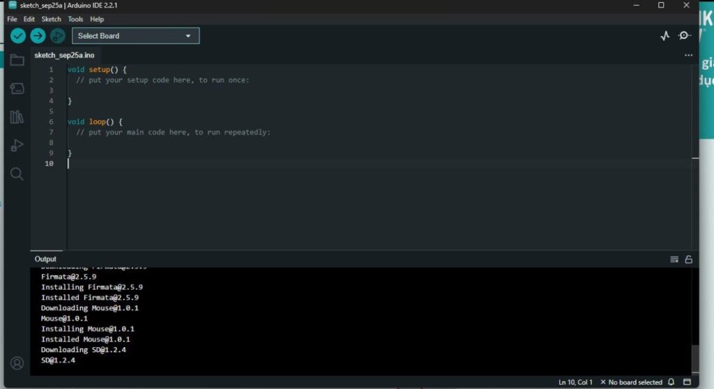
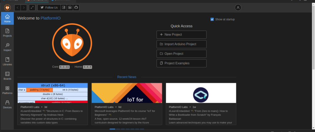
- Install extension open it and wait for the initialization When all done here is the result:
- The code we’ll use is C++ so you can install some extension for c/c++ to vscode also.
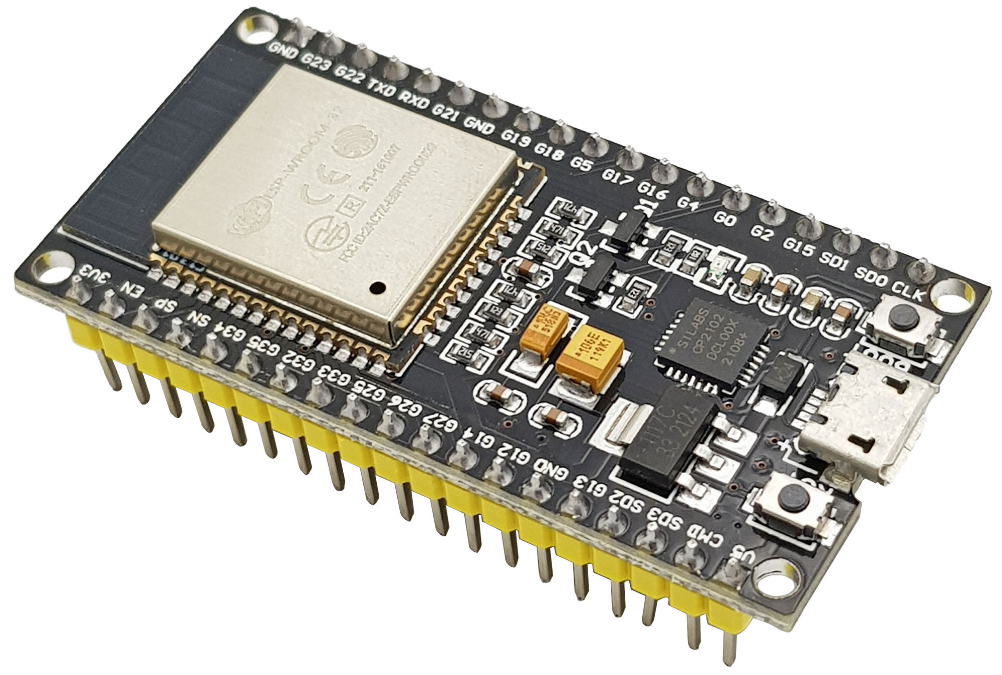
- Click at the New Project Button chose your board name(not too important but you can find your board name in your ESP32 microchip) along with your project name and project location
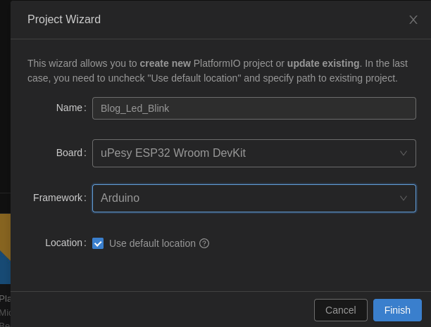
- Click finish then wait for project’s creation
2. Hello world with ESP32
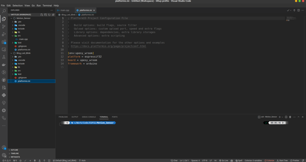
Here is how it look when all done look at the platformio.ini file this is the config file for your project. In this file you can see some informations about ESP32 board name the framework we’re using,… You can compare this file like packages.json when we work with nodeJs project cause when we can tell platformIO to install libraries by changing this file. Add this line to your platformio.ini
monitor_speed = 115200- This tell the baud rate of the serial monitor (I’ll explain latterr). Now open src main.cpp
#include <Arduino.h>

// put function declarations here:
int myFunction(int, int);

void setup() {
  // put your setup code here, to run once:
  int result = myFunction(2, 3);
}

void loop() {
  // put your main code here, to run repeatedly:
}

// put function definitions here:
int myFunction(int x, int y) {
  return x + y;
}
This is the boilerplate code that platformIO gave to us. All ESP32 code have to 2 main structures.
- The setup() function this function is called one when the board is boot up (when it have power plugged in or when we press RESET button (RST button)). So in this function we setup the logic for our board (ex: setup a PIN as a output or input mode)
- The main logic of your board is inside the loop() function code in here i a single thread loop so code in here will iterate forever. This loop() function run after setup() function and won’t stop if the board still have power
- So paste this code in your main.cpp
#include <Arduino.h>

void setup()
{
  Serial.begin(115200);
}

void loop()
{
  Serial.println("Hello, world!");
  delay(1000);
}
- Press the tick button to build your c++ code then press the arrow right button to upload your code to esp32. Remember to plug your esp32 to your computer. All these buttons is in the bottom bar of your vscode
- Note: if you have error like: no serial data found … please specific port. Follow this link to find your serial communication port: https://docs.espressif.com/projects/esp-idf/en/latest/esp32/get-started/establish-serial-connection.html. then add the port name to platformio.ini file
monitor_port = /dev/ttyUSB0 //or COM3 in window maybe your board will not use COM3 but i'm sure it is not COM1- Re upload your code and click to serial monitor to see the result
- Now you can see the serial monitor print hello world after 1s
- If you have error usually no serial data found please make sure
- You’ve installed all drivers in section 1
- Your cable can transfer data (some cable just transfer power from computer not allow data transfer)
- Your serial port by default platformIO will auto detect the port but linux /dev/tty0 or window COM1 is not the port for serial communication so if your platformIO try to connect this the error will occur
- For linux you need to add current user to dialout group too
sudo usermod -a -G dialout $USER3. The serial monitor
- Code explanation:
- In setup() function we open a connection to serial monitor using the Serial.begin() function. Serical monitor is a terminal where our PC can receive data from ESP32 and also send data to it. It like console when we code JS if you like to compare.
- The Serial.begin() function accepts one parametter. It is the baud rate. Baud rate is the read/write speed of serial monitor if you config the key monitor_speed in platformio.ini file the config value and the parametter must be same. If not you will see weird message (look like a wrong font) on sernial monitor
- Serial monitor is good for debugging testing our devices and program code
- Serial.println() a function to tell esp32 to print something to Serial terminal
- delay() make code follow stop in x milliseconds
4. Led blinking
Ok , let’s move on to build something more interactive print something to terminal is boring right?.
Let’s blink a led. Quick review led have 2 pin + and – connect – to a ground pin and + to a pin that can have power so the led will bright

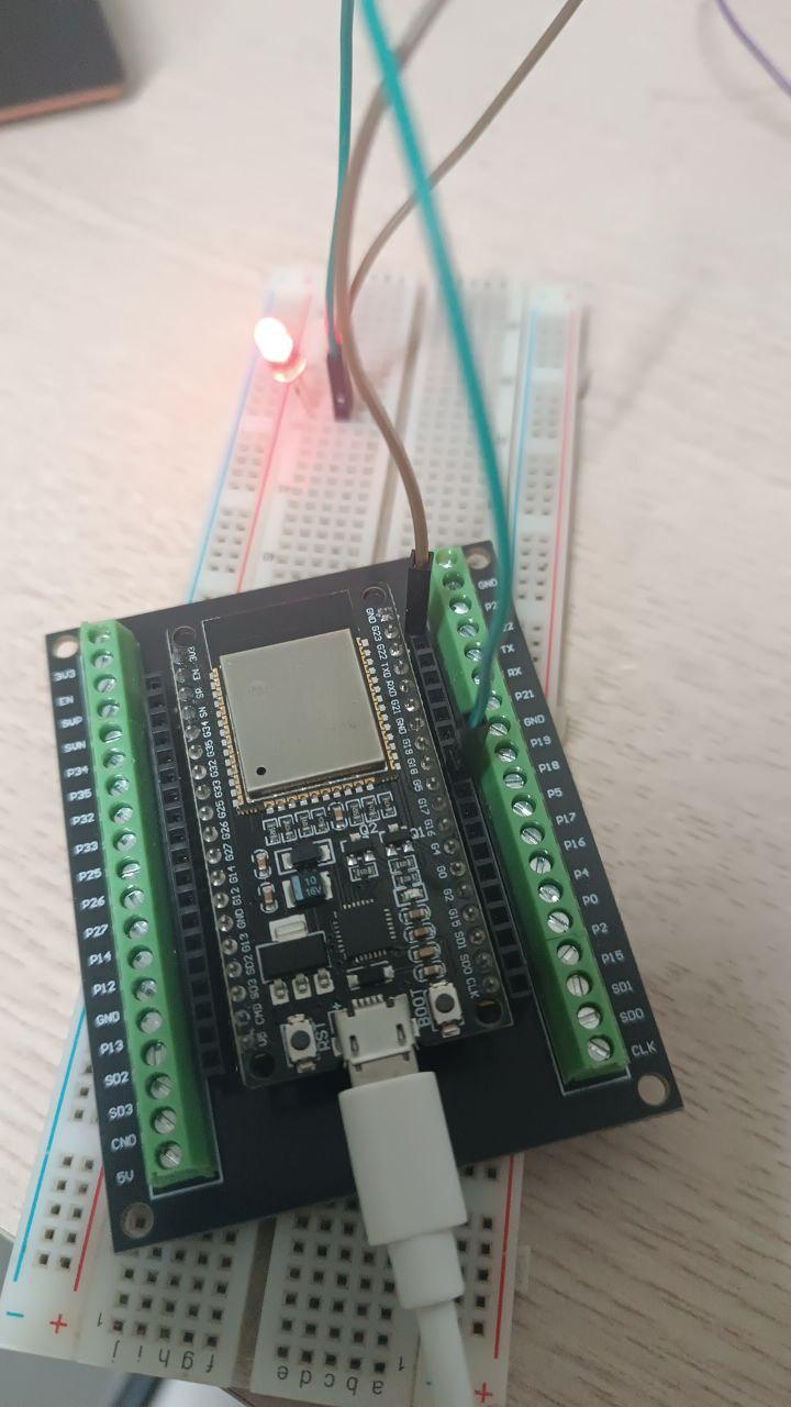
- Connect your led to your esp32 like this diagram
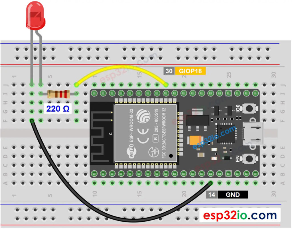
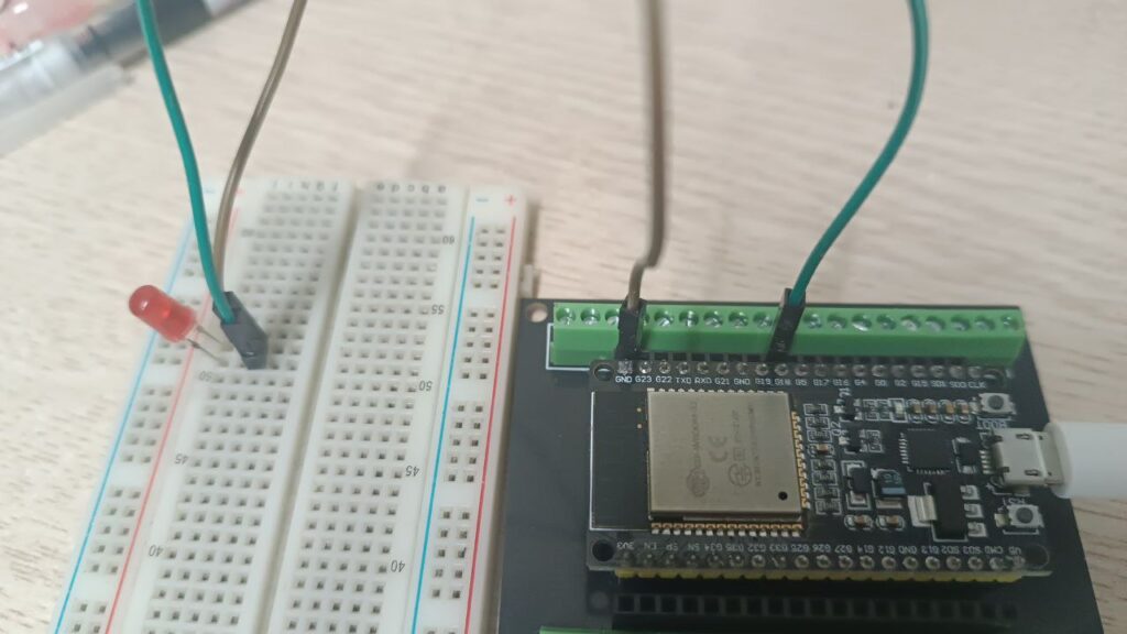
- The (-) pin connect to the GND pin the (+) pin connect to GIO 18 pin. You can see my setup with breadboard
- Now open vscode => open platformIO and create new project called led_blink or you can use the hello world project at section 1
- Let’s code
#include <Arduino.h>

void setup()
{
  Serial.begin(115200);

  pinMode(18, OUTPUT);
}

void loop()
{

  digitalWrite(18, HIGH); // turn the LED on
  delay(1000);

  digitalWrite(18, LOW); // turn the LED off
  delay(1000);
}- Paste this code to main.cpp then upload to esp32 and here is the result
Tada now the led is blinking after 1 second
- Code explanation, ok let’s walk through the code
- First, in setup() function i set the GPIO pin 18 is in output mode. Remember in part 1 of this series i told you that all ESP32 pins can be programmed as input pin or output pin so the pinMode() function accept 2 paramenter one is the pin to program and the other is the mode as OUTPUT or INPUT
- When the pin is output mode we can expose the power or write the voltage to it so digitalWrite() function help we do it digitalWrite(18, HIGH) means output voltage to pin 18 (it makes the led turns on) digitalWrite(18, LOW) means turn of the power on pin 18 (so the led will turn off because it have no power).
- We need to delay(1000) delay 1s after turn on or off the led otherwise the PIN 18 will have power then power off immediately which make led be turn off can not turn on or turn on can not be turn off
- It’s easy right with help of arudunio. library that we include at the top of the file buiding an ESP32 program is very easy
- If your led don’t blink make sure you connect the pin correctly (-) to GND and (+) to pin 18
Conclusion
Ok, now we’re doing something real with ESP32 blink a led is just a simple when you getting start with ESP32 but the concept about pin mode how we write the voltage is the basic building blocks that help us to build thing more interesting later. In next series we will learn about button the basic component when we use ESP32. See you soon. Thanks for reading <3
References
https://esp32io.com/tutorials/esp32-led-blink
__CodingCat__