Are you bored with web or software programing ? You want to learn something fun that something you’ve never experienced before. Welcome to IoT for noob series. Cause i just self learning Iot by myself so this for noob only :D. We will learn new conceptconcept about IoT step by step and build something really fun
0. Hardware preparation
- ESP32 microcontroller chip: https://shopee.vn/product/869927552/18877068795?gclid=CjwKCAjw38SoBhB6EiwA8EQVLkVSdLFt8vIU_zcu9F3CBH6kOsKizHahkKXINhZ9WdTmX6EQxx7HDhoCFe8QAvD_BwE
- BreadBoard (optional): https://shopee.vn/product/817071155/18024780678?gclid=CjwKCAjw38SoBhB6EiwA8EQVLsRU8GlGo3-HirWbGy90bGfaO4Wk9SRCRpIP7en73kmVpOjQQ-SjthoCYYEQAvD_BwE
- Jumper wires: https://shopee.vn/product/61435118/4504581993?gclid=CjwKCAjw38SoBhB6EiwA8EQVLmGQ_3jyEO8yKGen4R0cUofygZmjriiKM5MenxDHCQokzxQbwSb9jBoCTeEQAvD_BwE
- Leds: https://shopee.vn/product/26089641/14433324704?gclid=CjwKCAjw38SoBhB6EiwA8EQVLkf2c_I5axQLdrP11PZ5Jq3NaZuf75Tgp8IISUoJRnSzx15hGkGmuRoCunIQAvD_BwE
- ESP32 terminal adapter(optional): https://shopee.vn/product/129115042/15097704342?gclid=CjwKCAjw38SoBhB6EiwA8EQVLsNEEgvUsMe20TJdNsCwLRFeU_BLewcOi7exyOM_dhar30cw6INDYBoCJ4wQAvD_BwE
1. ESP32 overview
- When your shipper give all things you need. We can get start
- Do you ever wonder how a toy like remote car can work why the motor can run with a remote controller ? which make it is possible to control the motor speed and rotation direction ?. The answer is that all this toys have a microchip. Imagine this microchip is like a computer it has cpu, ram and also the driver for wifi and bluetooth connection and so on…
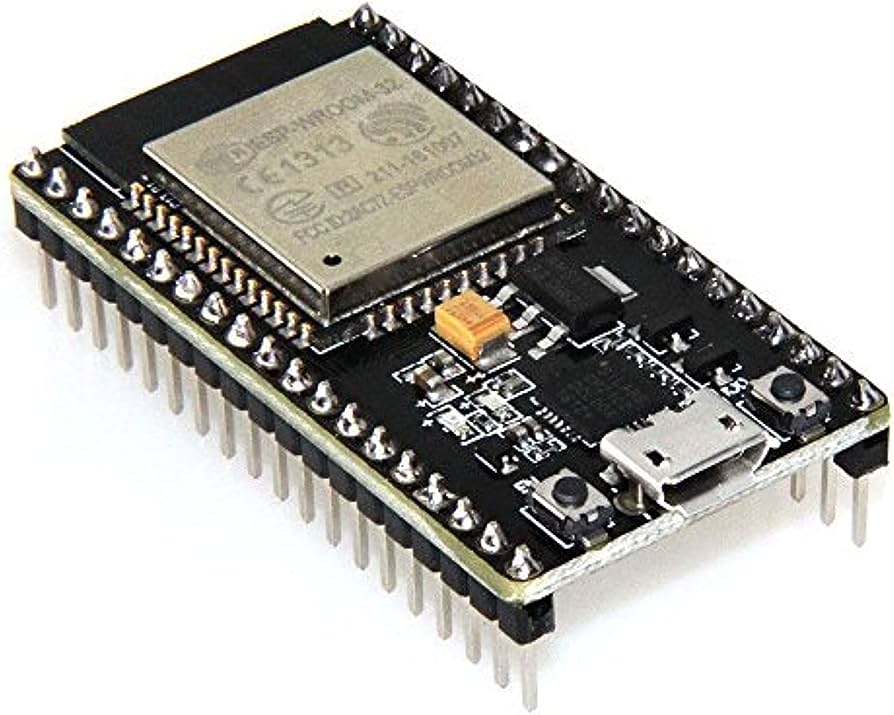
- This is exactly the ESP32 can do. The ESP32 is a versatile microchip designed for IoT and embedded applications. It features dual-core processing, integrated Wi-Fi and Bluetooth, low-power operation, and a rich set of peripherals, making it a popular choice for developers in creating connected devices.
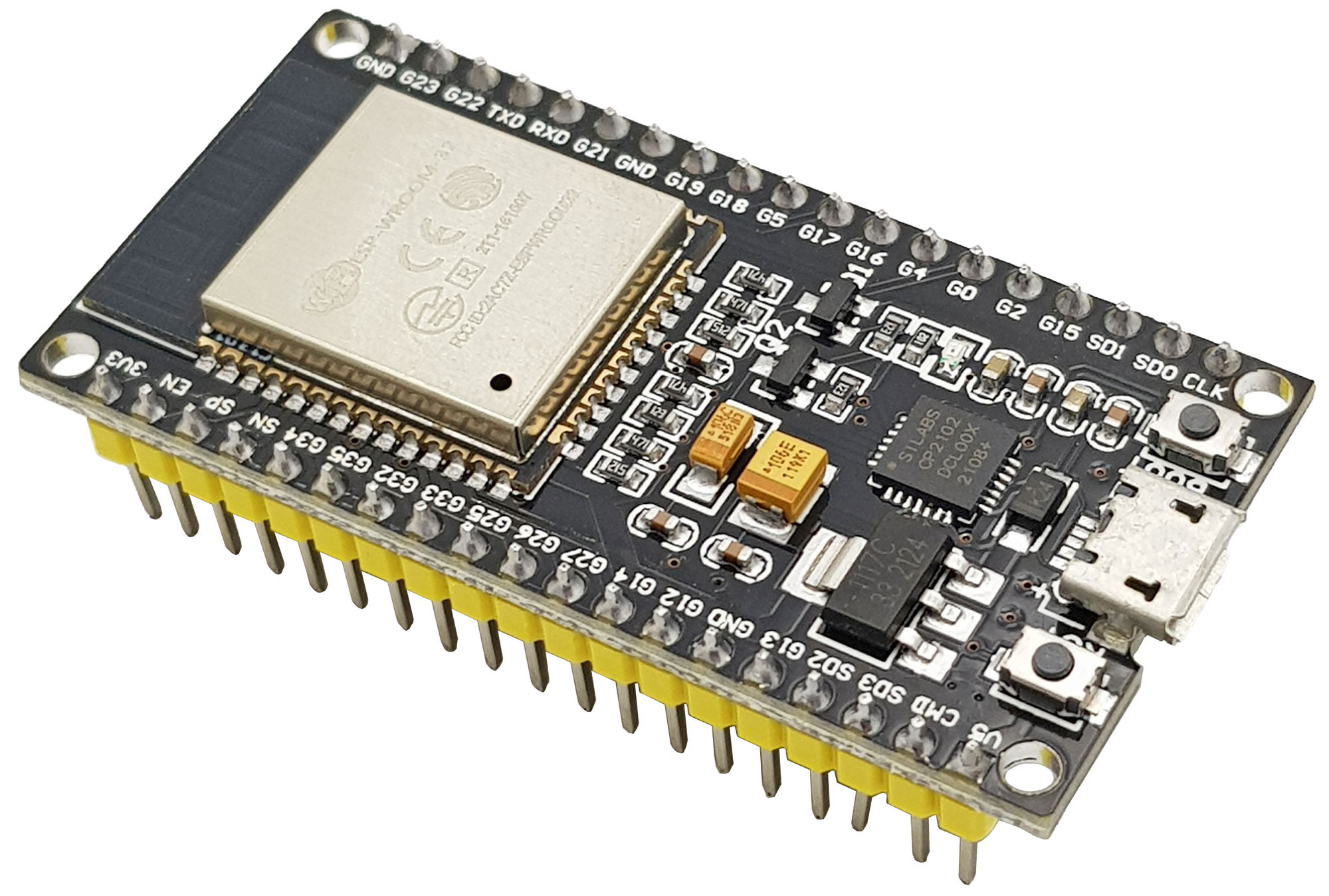
- Let’s take a look, you just need to pay attention at 3 main components .First is the micro USB port which help you to connect your ESP32 with your PC so that our board will have power and also can transfer data between esp32 and computer. Another component is the 2 built in buttons one is the boot button and another is reset button (we’ll talk about these 2 buttons latter). And last one is the GPIO pins there are a a lot of pins installed in the microchip (usually about 38 pins). These pins can be programmed base on what you want to do.
2. ESP32 GPIO pins
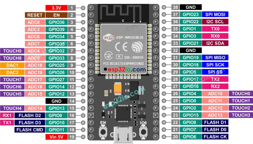
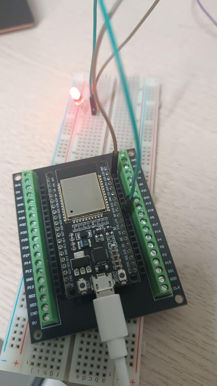
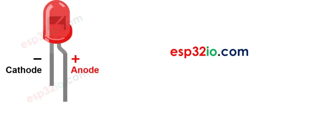
- Take a look at the diagram below and the ESP32 board that you’ve bought you can see along with GPIO (usually is mark by G1 or G2.. in the board) we also have a 3.3V pin 5V pin and Ground (GND) pins. In order to the devices work (ex light up a LED, make a sensor run) we need to provide it power. To supply the power to devices we connect the cathode pin(-) of device to the ground pin and the anode pin(+) to a VCC pin (or a GPIO pin that can write voltage by code for example). ESP32 have to default pin have a power of 3.3V or 5V on it. You can test it buy these steps:
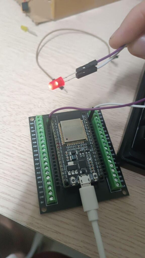
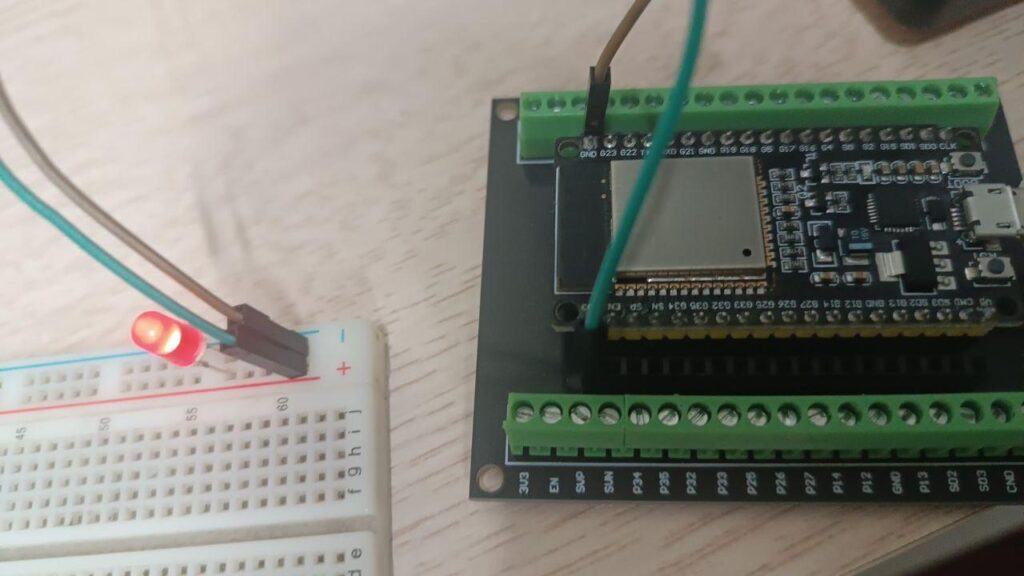
- First connect your esp32 to your power using the micro usb to usb type A cable. This will supply the power to our esp32 board
- Then connect the cathode (-) pin of the led (usually the shorter pin) to the one of the ground pin. And the anode (+) pin to the VCC pin (3.3V or 5V). After that the led will light up without anything else we need to do. To connect devices to board we use the jumper wires that we bought at part 0
- All these others GPIO pins we can programmed it as input or output pin.
- Output pin is a pin that can write the voltage or update device’s power status (ex: turn on or off a led by providing it the power or not).
- Input pin is a pin that can read (listen) to the power status changed (ex whether is pin have electricity or not) in most case the sensor we use send the result by changing the power status of it’s pin. So we connect this pin to a GPIO ESP32 pin. Set that GPIO pin as a input pin and monitor it’s power status to see the result of the sensor.
3. ESP32 Hardware usages
- In part one i recommend to buy some hardware that help you to play with ESP32. Now let’s see how we can use it and the functions of each device
3.1 The jumper wires
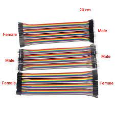
- Jumper wires help us to connect devices to devices or devices to ESP32
- Jumper wires have 2 pins is male and female. So base on this we have 3 types of jumper wires base on the pins: male to female, male to male and female to male wires
- Just plug it in and let’s the electric run :v
3.2 The screw terminal adapters
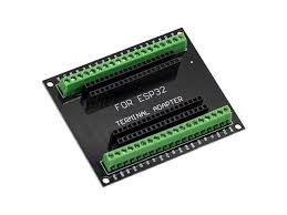
- This help secure your ESP32 connect all ES32 pins to the Screw terminal then we have 2 pins rows to connect to the ESP32 GPIO pins..
- The black inside row is for development plug the jumper wire to the correspond GPIO pin to connect to that pin
- The green outside row is when you done with development’s process. we connect screw the wire to it to fixed our wires’s connections make it stable when run in real world and in long terms.
3.3 The breadboard
- This is an optional tools but we should have to make our setting look cleaner and the connection between devices is much more easier
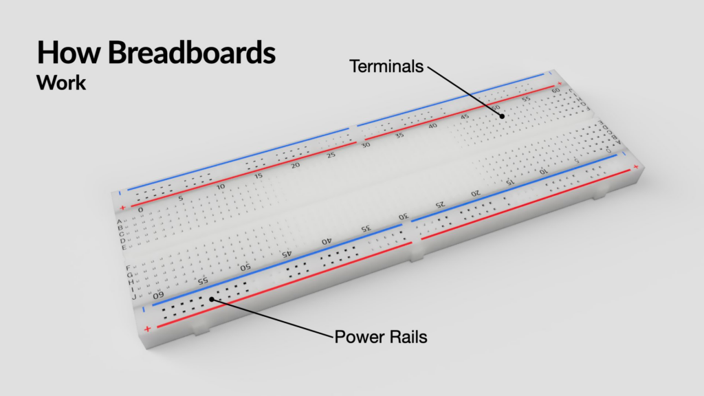
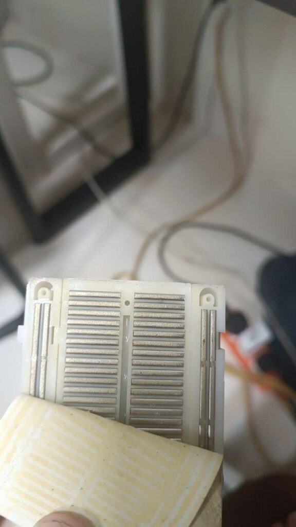
- You just need to notice how electronic run in this board. The 2 rows at the sides of the board the electricity goes vertically. These row at middles electricity goes horizontally. To see how electricity gose turn the back of the board and look at the coppers
- You can see the 2 rows in 2 sides have + – icon. so if you connect this + first pin to VCC PIN of ESP32 and the – first pin to the GND Pin of ESP32 all this row will have power. So the example that we light up the led in section 2 can light a lot of led using the breadboard:
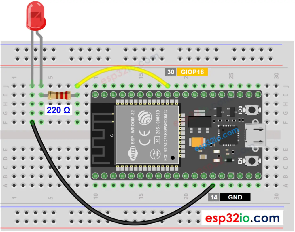
- Plug the cathode (-) pin of the led to the cathode row(-) and anode pin of the led (+) to the anode row(+) then use jumper wires to connect first + pin to 3.3v VCC Pin and first – pin to GND PIN
NOTE: for demo purpose so you can do it but for best practice we need to connect the led to a ohm resisor so that the power of the esp32 dont ruins the LED i’ve burned out about 2 3 led when try it to the 5V VCC pin of ESP32 LOL 😀
You can buy it here: https://shopee.vn/product/397654714/11631787706?gclid=CjwKCAjw38SoBhB6EiwA8EQVLgDgw9SeZViI2Qz4v2buYDr8qn2En52MN4AVyjKvLXd9n96xW6zYKBoCdjIQAvD_BwE
Conclusion
Ok we don’t code or do anything fancy in this blog yet cause we are just new to these things right getting start with IoT is not easy it took me 2 days just to print a hello world message and light up a led. But when we get used to the concepts the mechanic how our ESP32 works things get easier. And i will follow with you guys step by steps in these next blog of this series. See you soon
References
_CodingCat_